
 Industrial Automation


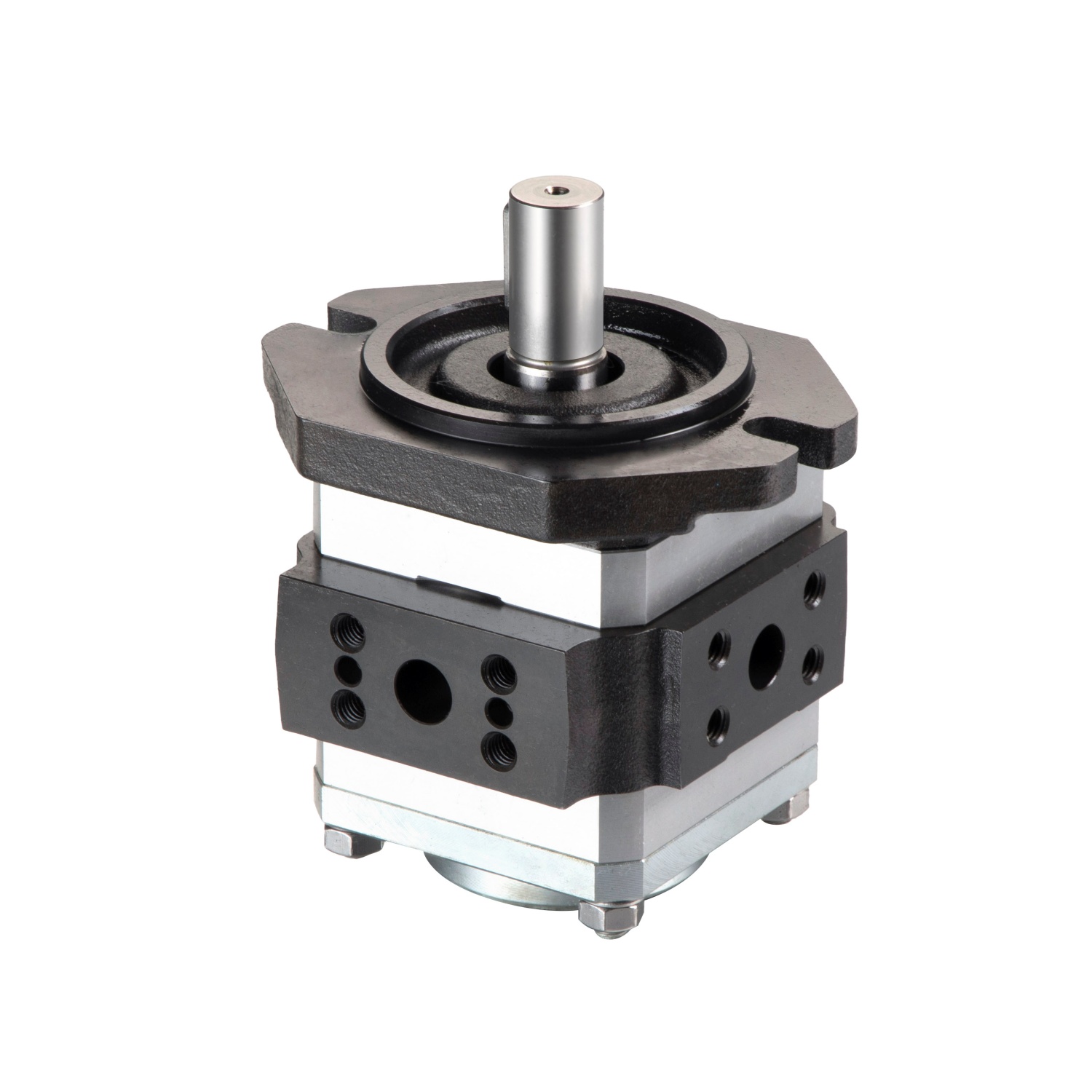


VG Series Internal Gear Pumps - High Pressure, Low Noise Pumps from China Suppliers & Factory
Experience the excellence of VG Series Internal Gear Pumps, expertly manufactured by Ningbo Vicks Hydraulic, a leading supplier in China. Our gear pumps are engineered for high pressure, ultra-low noise levels, and minimal pulsation, ensuring smooth, reliable operation in even the most demanding hydraulic systems.
Explore our extensive lineup of single pumps:
VGH0 Series: Designed to be compact yet powerful, this series offers displacements of 003 CC, 004 CC, and 005 CC. Operating efficiently at pressures up to 40 MPa and 4200 RPM, it meets niche low-flow and high-pressure needs that are hard to find in the market.
VG0 to VG2 Series: These versatile models range from 8 cc to 160 cc, providing reliable performance for a variety of industrial applications.
Whether for mobile machinery, industrial automation, or specialized servo systems, the VG Series stands out for its remarkable durability, efficiency, and precision. Trust our factory in China to deliver the high-quality hydraulic solutions your business needs.
Model Representation

Model Representation
| VG1 | -63 | R | E | W | -A1 |
| Series | ml/r Displacement | Rotation | Shaft type | Sealing material | Design number |
| VGH0 | 003, 004, 005 |
Viewed from shaft end of pump R = Right hand for clockwise L = Left hand for counter-clockwise |
K = Straight key shaft |
W = (Buna) NBR V = (Viton) FKM |
1K |
| VG0 | 8, 10, 13, 16, 20, 25, 28 |
E = Straight key shaft R = SAE Spline shaft |
A1 | ||
| VG1 | 25, 32, 40, 50, 63 50H, 63H |
||||
| VG2 | 80, 100, 125, 145, 160 |
Technical Data

| Series | ml/r | ml/r | MPa | MPa | r/min | kg |
|---|---|---|---|---|---|---|
| Displacement | Theory Displacement | Rated Pressure | Max. Pressure | Max. Speed | Weight | |
| VGH0 | 3 | 3 | 33 | 40 | 4200 | 4.6 |
| 4 | 4 | 4.8 | ||||
| 5 | 5 | 4.8 | ||||
| VG0 | 8 | 8.2 | 31.5 | 35 | 3000 | 4.6 |
| 10 | 10.2 | 4.8 | ||||
| 13 | 13.3 | 4.9 | ||||
| 16 | 16 | 5.2 | ||||
| 20 | 20 | 25 | 30 | 5.6 | ||
| 25 | 24 | 6 | ||||
| 28 | 27 | 6.4 | ||||
| VG1 | 25 | 25.3 | 31.5 | 35 | 14.5 | |
| 32 | 32.7 | 15 | ||||
| 40 | 40.1 | 16 | ||||
| 50 | 50.7 | 17 | ||||
| 63 | 63.7 | 25 | 30 | 18.5 | ||
| VG2 | 80 | 81.4 | 31.5 | 35 | 43.5 | |
| 100 | 100.2 | 45.5 | ||||
| 125 | 125.3 | 48 | ||||
| 145 | 145.2 | 25 | 28 | 50 | ||
| 160 | 162.8 | 21 | 26 | 52 |
Characteristic & Noise Curves
1500r/min Characteristic curve

2000r/min Characteristic curve

1500r/min Noise curve

2000r/min Noise curve

VGH0 Installation Dimensions

VG0 Installation Dimensions

| Model | L1 | L2 | A | B | C | D | E | F | G |
|---|---|---|---|---|---|---|---|---|---|
| VG0-08 | 107 | 54 | 38.1 | 17.5 | Φ13 | M8 Depth 13 | 47.6 | 22.2 | Φ19 |
| VG0-10 | 111 | 56 | 52.4 | 26.2 | |||||
| VG0-13 | 117.5 | 59.25 | |||||||
| VG0-16 | 123 | 62 | |||||||
| VG0-20 | 131 | 66 | 47.6 | 22.2 | Φ18 | M10 Depth 15 | 58.7 | 30.2 | Φ26 |
| VG0-25 | 139 | 70 | Φ19 | Φ28 | |||||
| VG0-28 | 145 | 73 |
VG1 Installation Dimensions


| Model | L1 | L2 | A | B | C |
|---|---|---|---|---|---|
| VG1-25 | 139 | 73 | 47.6 | 22.2 | Φ18 |
| VG1-32 | 146 | 76.5 | |||
| VG1-40 | 153 | 80 | 52.4 | 26.2 | Φ20 |
| VG1-50 | 163 | 85 | |||
| VG1-63 | 177 | 92 | |||
| VG1-50H | 163 | 85 | see page 11 oil port size | ||
| VG1-63H | 177 | 92 | |||
VG2 Installation Dimensions


| Model | L1 | L2 | A | B | C | D | E | F | G | H |
|---|---|---|---|---|---|---|---|---|---|---|
| VG2-80 | 204 | 109.5 | 69.9 | 35.7 | Φ32 | M12 Depth 20 | 77.8 | 42.9 | Φ51 | M12 Depth 20 |
| VG2-100 | 213 | 114 | ||||||||
| VG2-125 | 225 | 120 | 79.4 | 36.5 | Φ38 | M16 Depth 25 | 88.9 | 50.8 | Φ63.5 | |
| VG2-145 | 235.5 | 124.75 | ||||||||
| VG2-160 | 243 | 129 | 106.4 | 61.9 | Φ76 | M16 Depth 25 |
VG series single pump inlet and outlet oil port connection size

| Model | Specifications | S | A1 | B1 | C1 | Corresponding flange | P | A2 | B2 | C2 | Corresponding flange |
|---|---|---|---|---|---|---|---|---|---|---|---|
| VG0 | 8 | 19 | 47.6 | 22.2 | M10 Depth 15 | F06 | 13 | 38.1 | 17.5 | M8 Depth 13 | F04 |
| 10 | 52.4 | 26.2 | F08 | ||||||||
| 13 | |||||||||||
| 16 | |||||||||||
| 20 | 26 | 58.7 | 30.2 | F10 | 18 | 47.6 | 22.2 | M10 Depth 15 | F06 | ||
| 25 | 28 | 19 | |||||||||
| 28 | |||||||||||
| VG1 | 25 | 32 | 58.7 | 30.2 | M10 Depth 17 | F10 | 18 | 47.6 | 22.2 | M10 Depth 17 | F06 |
| 32 | |||||||||||
| 40 | 20 | 52.4 | 26.2 | F08 | |||||||
| 50 | |||||||||||
| 63 | |||||||||||
| 50(H) | 38 | 69.9 | 35.7 | M12 Depth 20 | F12 | ||||||
| 63(H) | 51 | 77.8 | 42.9 | F16 | |||||||
| VG2 | 80 | 51 | 77.8 | 42.9 | M12 Depth 20 | F16 | 32 | 69.9 | 35.7 | M12 Depth 20 | F12 |
| 100 | |||||||||||
| 125 | 63.5 | 88.9 | 50.8 | F20 | 38 | 79.4 | 36.5 | M16 Depth 25 | F14 | ||
| 145 | |||||||||||
| 160 | 76 | 106.4 | 61.9 | M16 Depth 25 | F24 |
Product Display